3D Point Cloud
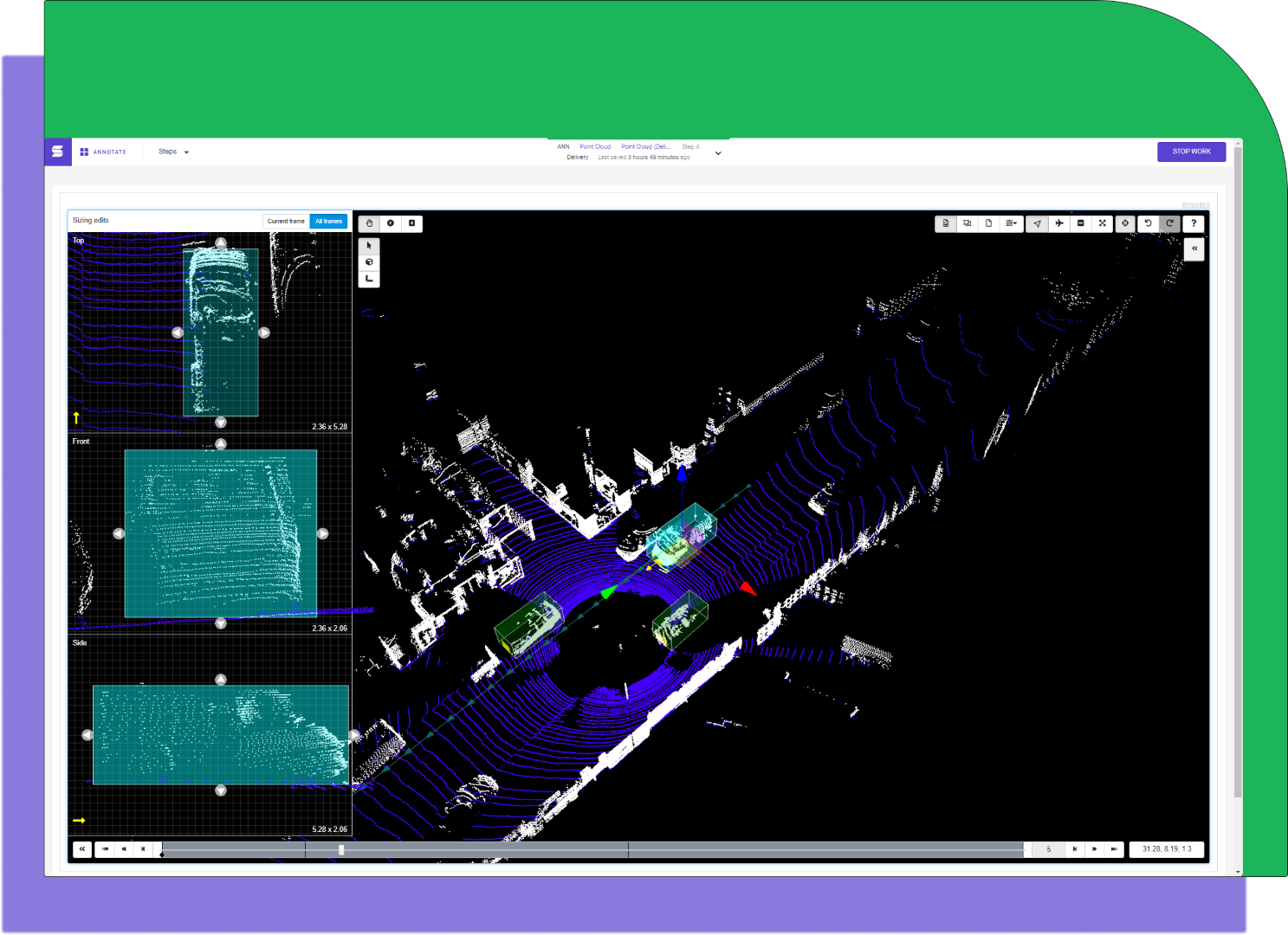
Point Cloud is a type of workspace output often used for LIDAR data. Each point has three dimensions (x, y, and z coordinates), as well as an optional intensity value. Much like a video, the point cloud data is captured over time, and associates will scrub through the asset annotating objects. The Point Cloud output is often used for autonomous driving use cases and will resemble the following:

An example workspace of a 3D Project
Coordinate System
The Sama platform uses the right-handed Cartesian coordinate system, and the positive z direction must represent “up” in the physical world.
Sama uses the roll-pitch-yaw XYZ Euler angle convention where roll is around the x-axis, pitch is around the y-axis, and yaw is around the z-axis.
Fixed world
Fixed world refers to a 3D environment that is anchored to the world, rather than a 3D environment that is relative to a moving object like the ego vehicle. Annotating in a fixed-world environment can be much faster and result in better quality, especially with static objects, as they mostly stay in place as the scene progresses.
Whether the point cloud coordinate system origin is a fixed point on the ego vehicle or a fixed point in world coordinates, any pre-annotations, camera calibration or odometry data must be given in that same coordinate system. Annotations will be delivered in the same coordinate system as the point cloud
Point cloud data is typically delivered in its local coordinate system that uses the LIDAR camera as the frame of reference, but fixed-world 3D environments require that the point cloud data use the world coordinate system. When this setting is enabled, the platform will pre-process your point cloud data into the world coordinate system (you will also need to provide sensor location metadata in a separate input).
Sensor location metadata
The sensor location metadata describes the LIDAR sensor’s position and what direction it's pointing, and is required to enable fixed world. This is also known as the LIDAR extrinsic matrix. The metadata is given for each frame and contains values of:
- Position [x,y,z] - the position of the sensor regarding a world frame.
- Rotation [rotation_x,rotation_y,rotation_z,rotation_w] - Also known as the heading/orientation, which represents the orientation of the sensor regarding a world frame. Values should be in a quaternion.
There are sensor location metadata files for each point cloud frame, and the total number of sensor location metadata files must match the number of point cloud frames/files. The accepted formats are CSV (.csv or .txt) or JSON (.json), and these files must be zipped together into a .zip file (unless the assets are on the sama-client-assets S3 bucket, in which case they can be in a folder).
Supported formats
Sama supports the following point cloud data formats from LIDAR and other 3D sensors, as supported by PDAL:
- .bpf
- .csd
- .ept
- .e57
- .gdal
- .geowave
- .i3s
- .ilvis2
- .las
- .matlab
- .mbio
- .mrsid
- .nitf
- .npy
- .pcd (in text or binary uncompressed; binary compressed is not supported)
- .ply
- .pts
- .qfit
- .txt
Additional types
If you require any other format, reach out to our team for further assistance.
Each data point must have (x,y,z) coordinates.
Point intensity values are also optionally supported (normalized to a 0-1 scale), encoded in an intensity dimension. Intensity values can also be normalized via project settings. Please share example files with your project manager early in the scoping process.
The following dropdown demonstrates the file structure needed using zip files. Folders are also supported in place of zips, and follow the same file structure, but must be uploaded to Sama's secure AWS S3 bucket.
Sensor fusion support
Please see additional notes below on folder support. It’s required to keep the assets in a correct and matching sequence for sensor fusion to be properly supported.
Testing the compatibility of a point cloud file
To test whether your point cloud file is compatible with the Sama platform:
- Install PDAL from https://pdal.io/quickstart.html.
- Run “pdal translate lidar.pcd”.
This will attempt to do a vanilla translation from the input format to .pcd. If an error occurs, the file will not load in the Sama platform.
Point Cloud tools
Cuboid (3D)
The (x,y,z) vertices of each 3D cuboid are always exported in the following pattern: one full face and then the other full face. In this diagram, the side bounded by 3-1-2-0 is one face of the cuboid and the side bounded by 7-5-6-4 is the other face of the cuboid. These faces may be “front” and “back,” “left” and “right,” or “top” and “bottom,” depending on the cuboid’s rotation in the data.
The cuboid vertex export order can be used to define a face of interest. The face of interest is defined by the first four vertices of the cuboid listed in the export file. A face of interest, or side of the cuboid, can be used to designate the front of a car or the direction of movement of an object bounded by a cuboid. Therefore, there is always a default face of interest.

Cuboid vertex export pattern, showing the first 4 vertices exported as the “front” and the last 4 vertices exported as the “back.”
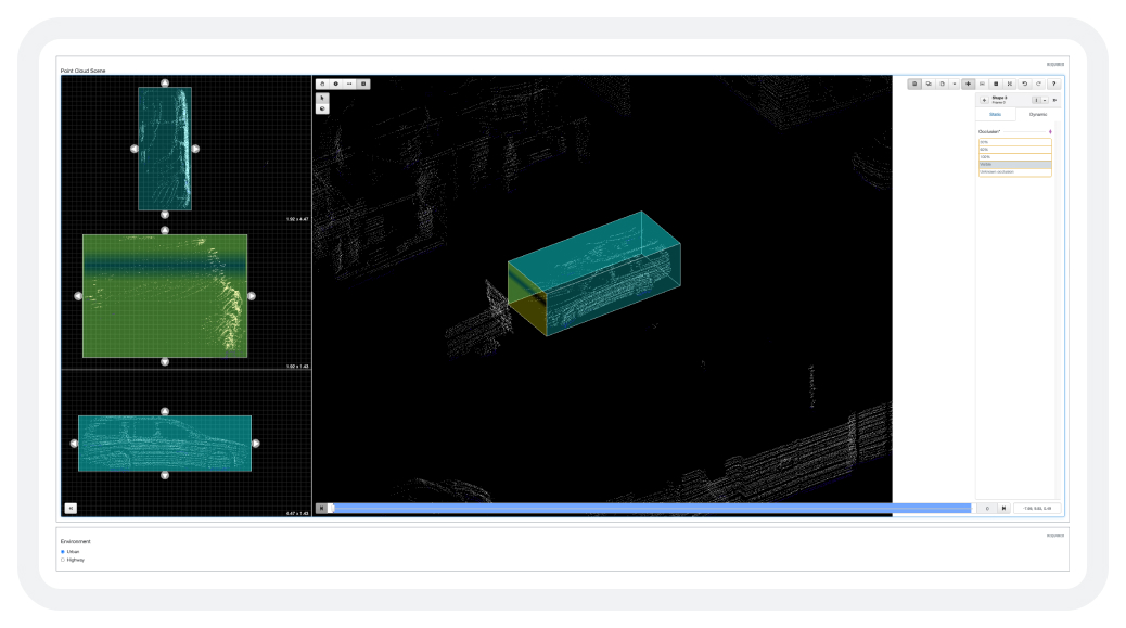
As an illustrative example, consider the Point Cloud workspace below, where a single vehicle has been delimited by a cuboid.

The JSON for this object would be as follows:
"Point Cloud Scene": [
  {
    "shapes": [
      {
        "tags": {
          "Parent": "None",
          "Answers": "TYPE_VEHICLE",
          "Occlusion": ""
        },
        "type": "cuboid",
        "index": 3,
        "key_locations": [
          {
            "tags": {
              "Occlusion": "Visible"
            },
            "points": [
              [
                -2.64196,
                3.93875,
                -1.82775
              ],
              [
                -2.64196,
                3.93875,
                -0.40086
              ],
              [
                -2.64196,
                5.85652,
                -1.82775
              ],
              [
                -2.64196,
                5.85652,
                -0.40086
              ],
              [
                1.83147,
                3.93875,
                -1.82775
              ],
              [
                1.83147,
                3.93875,
                -0.40086
              ],
              [
                1.83147,
                5.85652,
                -1.82775
              ],
              [
                1.83147,
                5.85652,
                -0.40086
              ]
            ],
            "visibility": 1,
            "frame_number": 0,
            "position_center": [
              -0.40525,
              4.89764,
              -1.1143
            ],
            "direction": {
              "roll": 0.0,
              "pitch": 0.0,
              "yaw": 3.141592653589793
            },
            "dimensions": {
              "length": 4.47343,
              "width": 1.91777,
              "height": 1.42689
            }
          }
        ],
        ...
 }
- The first 4 points represent the face of interest.
- The
position_center(x,y,z) is the center point of the cuboid. - Dimensions are the length(along x-axis), width(along y-axis) and height(along z-axis) of the cuboid.
- Direction is the roll, pitch, and yaw of the cuboid; applied in that respective order and in radians. Using direction, it is easy to determine any faces of interest (such as the front of a cuboid that may represent the front of a vehicle). For specific faces of interest that depend on annotation instructions, use points as above.
Updated about 2 years ago
